Misc. Information and Knowledge Bank
***PLEASE NOTE: THE REMOVAL OF ANY GEARBOX REQUIRES A NEW CENTERING BUSHING, EVERY TIME***
Gearbox Mounting Bolt Torque:
1/2 Bolt - 70 ft.lb
3/8 Bolt - 25 ft.lb
5/16 or 8 mm Bolt - 18 ft.lb
Motor Mount Bolt Torque:
200 inch lbs
Cracked Coolant Fitting Repair (if needed)
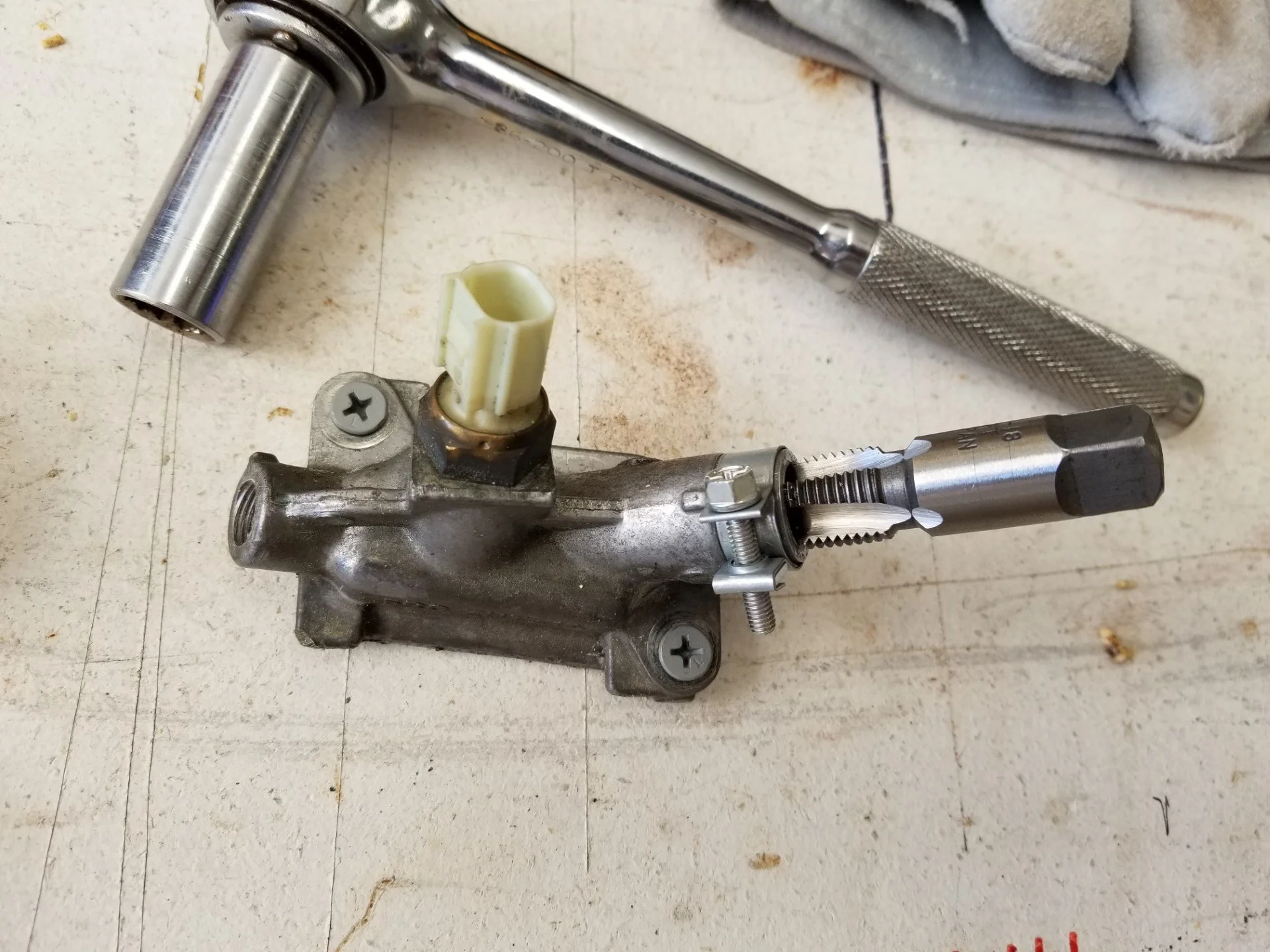
I removed the fitting from the engine (photo 1), at which time I could see the small crack on the underside (photo 2, with arrow). I lightly inserted a 1/4NPT tap into the broken fitting so I could get a measurement of how deep I would need to tap later in order to maintain the same "clock position" for a 90 degree brass fitting that needs to be there (photo 3). When I had the tap screwed in finger tight, I simply counted the number of threads that were exposed (on the tap) and thus knew that when I threaded it again, that was "how deep" it needed to go.
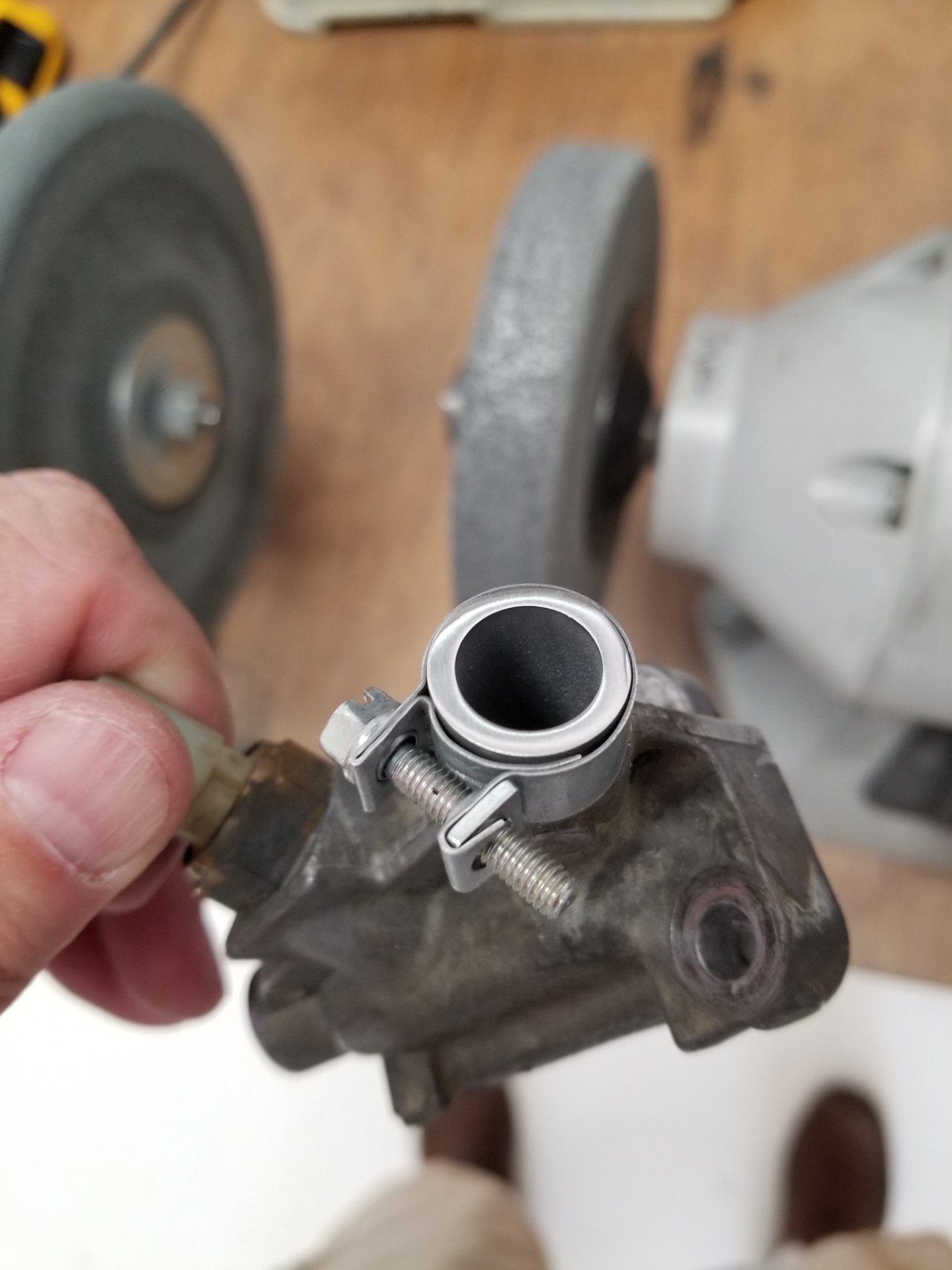
Photo 4 shows a Fuel Injection Clamp being used. This was to help guide a band saw blade while I cut the cracked material off, as well as to support the metal casting when I re-tapped it. After cutting the old metal off, I polished the edge to a mirror finish with the idea of eliminating stress risers in case it wanted to crack again when I re-tapped it (photo 6).
As it turned out, the metal towards the base of the casting is thicker than it is out on the end of the nipple, so the clamp may be overkill (photo 7). But I left it on as I could see no downside to doing that. Perhaps an appropriate size of Oetiker clamp would have been better, but I simply used what I had available and it is working well.
I believe the correct name for this thing is "Cover, Water Outlet", having Part Number 19315-5R0-000. I ordered a new one from https://www.hondapartsnow.com/ just in case I messed this one up, although it appears that I won't need it one as my old one is functioning better than ever. -Hoyt
Viking Daily Tech session - FUEL
How to recognize a fuel vapor lock or other fuel starvation issue with a Viking Engine and how to prevent it from happening along with fuel system knowledge and updates.
In general, it is hard to have any issues related to vapor lock in an injected engine. The fuel is only at atmospheric pressure between the main wing and the header tank. After the fuel leaves the header tank, it is under pressure and vapor lock is very unlikely.
Well, the summer is here and temperatures are likely to be hot, so let’s talk about the systems and what to look out for.
Let’s start at the wing tanks and work our way towards the engine.
Fuel will drain from the wing tanks to the header tank if the header tank is vented to the wing tanks and the wing tanks are vented to the atmosphere. On low winged aircraft, these atmospheric vents should have elbows on them, facing forward into the relative wind to add some fuel tank pressure. Low winged aircraft should also have the left and right tank tied together as one, into the “mini” header tank, without any fuel valves.
The ON / OFF valves on all systems are the fuel pump switches. Wing tank and header tank drains are used but no gascolator. It is less important to have a drain on the “Mini” header tank.
Inline filters are used prior to the header tank. Earlier in-tank fuel pumps, those mounted from the bottom up, should have their small on-pump filters removed, according to the Viking service bulletins.
Header tanks feeding a direct injected engine all have a 0.010 bleed orifice from the pump output side, back to the header tank to eliminate the build up of pressure while parked, if the high pressure side on the engine were to leak any fuel back through the mechanical pump. This prevents excessive pressure on the hoses. Port injected engines should be updated and install the orifice to bring fuel pressure in the hoses to zero between flights. This will help with fuel expansion in the large engine fuel rail, also causing excess pressure on the hoses and making the engine harder to start after being parked on a hot ramp. A vent should also be made above the fuel rail on port injected engines to prevent heat soak when parked.
The fuel pumps are good for 10 years with regular use. They can be on together all the time if you verify that they each work. For long cross country flights, one is usually turned off, along with one battery.
The one exception is for the “mini” header tank. Just use one pump when the engine is not consuming much fuel, such as idling and ground operations. Two pumps will just unnecessary build fuel temperature in the small tank. At higher power settings, this is no longer an issue since fresh fuel is flowing into the tank.
After the header tank, there is a check valve for each pump to prevent fuel returning through the backup pump. If you ever have a situation where you are not able to build fuel pressure, one of these could be a suspect.
Then the fuel flow through a high pressure filter and to the fuel rail. The fuel pressure when you first power up should be close to zero on a direct injected engine and 40-60 after the pumps are on. For a port injected engine, like the 90, 110, 150 and 175 hp, the pressure will be between 0 and 45, depending on how long the engine has been sitting. If the pressure is higher than this, be aware of a potential vapor in the fuel rail, pushing the pressure above normal. This will disappear once updated with a pressure bleed and by venting the top of the cowling.
I am starting a daily “Technical Questions“ for fun, safety and education.
Here is the first one:
What is the main downside of setting a fine pitch / higher rpm on the engines for a system using a ground adjustable propeller. Also, why is it more of a drawback than with a traditional style airplane engine?
ANSWER:
And the answer to today's question is: Pumping losses. The more open the throttle can stay, the more efficient the engine can operate. "B-29 crews in World War 2 found that when unloaded, their four-engine aircraft could fly farther on three running engines and one engine stopped (and its prop feathered to minimize drag) than they could with all four turning. Why? Because cruising speed with just three engines required opening their throttles more, reducing pumping loss." Pumping losses refer to the power required to perform the intake and exhaust pumping functions in spark-ignition piston engines. Here’s how it works:
Intake Stroke: During the intake stroke, the pressure acting on top of the piston is the intake manifold pressure. However, there are pressure losses as the intake charge passes through the intake port and valve. These losses contribute to pumping losses.
Throttle Effect: At low speeds, gasoline engines suffer efficiency losses due to high turbulence and frictional losses when the incoming air must fight its way around the nearly closed throttle (known as pump loss).
Minimizing Pumping Losses: To minimize pumping losses, engineers employ strategies such as optimizing intake and exhaust system design, using variable valve timing, and improving overall engine efficiency.
Remember that these losses can account for up to 10% of the total engine power output. Under part throttle conditions (i.e. when the throttle is less than fully open), the effective compression ratio is less than when the engine is operating at full throttle, due to the simple fact that the incoming fuel-air mixture is being restricted and cannot fill the chamber to full atmospheric pressure. The engine efficiency is less than when the engine is operating at full throttle. One solution to this issue is to shift the load in a multi-cylinder engine from some of the cylinders (by deactivating them) to the remaining cylinders so that they may operate under higher individual loads and with correspondingly higher effective compression ratios. This technique is known as variable displacement. So, to maximize the efficiency of the Viking Engine, it is useful to fly with the throttle wide open. This is easy to do with a variable propeller because power output and RPM can be reduced by adding pitch to the propeller, while the throttle is fully open to optimize the intake flow. With a fixed propeller, one way to do this is to operate at a low RPM during takeoff and climb in order to leave as much throttle as possible during cruise. With a higher initial rpm, the only way to reduce the rpm for cruising is to restrict the airflow by closing the throttle plate, thereby creating a restriction that the downward moving piston has to suck air around. So, to simplify: The lower the takeoff RPM, the more efficient and faster the cruising will be because less throttle restriction has to be used to achieve the cruising RPM. With a modern engine, equipped with variable ignition and valve timing / knock sensing, this operation is allowed and does not harm the engine in any way.
Daily Tech Question
Why is it important to use 2 batteries when starting the Viking engines?
Answer:
The answer is based on what the system was intended for and how a pilot should view it while operating it. From experience, a dual battery system is not helpful in real life. Pilots will land in a field with a fully charged secondary system, if it is complicated.
Therefore, the Viking battery system should be viewed as a single system, with the ability to put half of the electrons on standby during cruising flight, away from an airport.
Mechanically, when the two master switches are on, the two batteries become one bigger battery. Each battery, on its own, does not have the wire sizes needed to reliably start the engine due to the small terminals on the battery itself. (Yes, it can be done but not intended that way)
So, we have "one" big battery, with the ability to put half on standby. We want to start the engine on the big battery, taxi and take off on the big battery so it can be charged by the alternator. We want to fly all of our local flight on the big battery and anytime we are flying close to the ground. (The BIG battery being the two smaller units tied into one)
The ONLY time we put half of the capacity on standby, is when we leave the airport and head out on a longer flight. A flight where, if we lost charge on our battery from the alternator, and we somehow did not detect it from our battery warning instrumentation, we would be able to keep everything going by turning on the standby power.
By operating like this, the big battery is constantly being charged and is ready to be divided when appropriate. As far as the responsibility of the pilot, the procedure of placing half on standby should be noted on the checklist and is done when you leave the airport or 15 minutes into the flight.
The opposite is also true. If the batteries were left together and at some point the charging from the alternator was lost, the procedure is to then put one on standby in order to separate the remaining capacity.


