SENSOR LOCATIONS, EIS & VIKING VIEW
***PLEASE NOTE: THE REMOVAL OF ANY GEARBOX REQUIRES A NEW CENTERING BUSHING, EVERY TIME***
Our engines are compatible with any Garmin, Dynon, MGL etc. You need to request the following from them for your engine needs.
The video below shows where all the sensors go (regardless of the EIS you choose)
Our engine is not like a Lycoming/Air cooled engine - there is no need for things like CHT EGT etc. the glory of true fuel injection is the elimination of things like CHT and EGT and the monitoring involved.
All Engines:
RPM - our ECU provides one pulse per revolution. (some installations will require a 1K pull-up resistor to 12V) 6000 RPM limit
ENGINE OIL TEMP - We do not measure this.
GEARBOX OIL TEMP - 1/8 NPT temperature probe - 250 max temp.
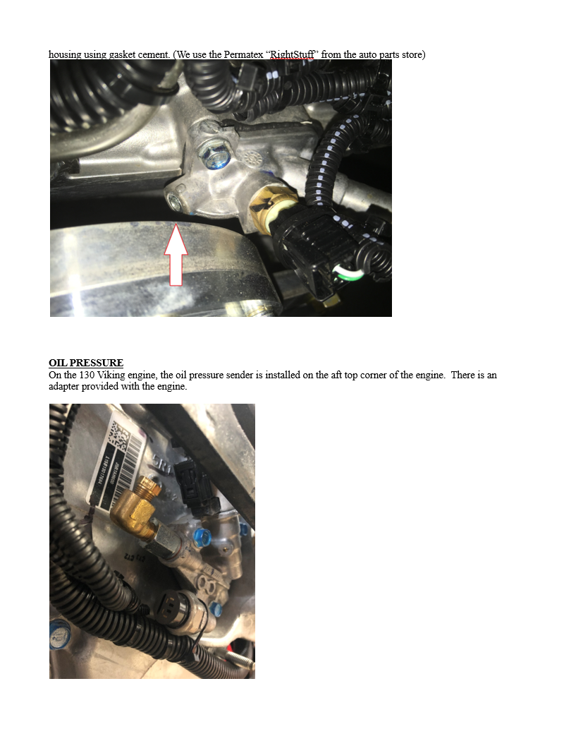
COOLANT TEMP* - 1/8 NPT temperature probe.
OIL PRESSURE - 1/8 NPT transducer capable of reading 0 - 100 psi.
We don't measure oil temp. We are against it because it is just another failure point where you could lose the oil. Modern oils have a very high limit to the temperature, so the governing factor becomes the pressure not the temperature.
FUEL PRESSURE - 1/8 NPT transducer capable of reading 43 psi.
VOLTAGE - EFIS reads system voltage
Additional Sensors for the 195 Turbo Engine:
INTERCOOLER INLET TEMPERATURE - 1/8 NPT temperature probe - 250 max temp.
INTERCOOLER OUTLET TEMPERATURE - 1/8 NPT temperature probe - 150 max temp.
MANIFOLD PRESSURE - 1/8 NPT transducer - 12 psi. (55” of Manifold Pressure)
*Coolant temperature varies dependent on engine - reference website
GENERATION 2 VIKING VIEW
A basic engine monitor for the Viking engine with applicable sensors and ready to go. Unit also comes with a front bezel.
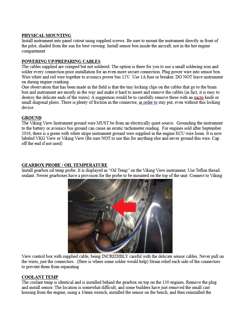
Pre-wired and ready to install/use engine monitor. This engine monitor is specific to the Viking Engine lineup. At this time, the non-turbo models are supported with a future announcement for when the turbo engines will be included. The box includes the sunlight readable instrument, all wires terminated to a terminal strip, as well as wires from the terminal strip to the individual probes. The four probes are:
Gearbox Temperature
Coolant Temperature
Fuel Pressure
Oil Pressure
The instrument also displays RPM and voltage and has a bright external warning light already wired in.
Usually when purchasing an engine monitor you would normally receive a box with a gauge, some wiring pins and a thick manual. The Viking View works right out of the box. Use a small battery and a 1 AMP fuse to power it up. Everything immediately works, all you have to do is transfer everything in the box to the instrument panel and engine.
All parameters are pre-set for you and your engine model.
Please see our technical video under EIS/Sensor locations for your applicable engine
Dynon Sensor Part Numbers:
For Viking 90, 130 and 150 engines:
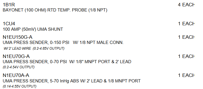
Oil Temp Sensor (x2) 100409-000
Oil/Fuel/Fluid Pressure Sensor (x2) 103757-000
For Viking 195T engine:
Oil Temp Sensors (x4) 100409-000
Oil/Fuel/Fluid Pressure Sensor (x2) 103757-000
Manifold Pressure 100434-000
Please note, this is the most recent information we have, please double check with Dynon what the needs would be.
The EMS220/A is what is used for engine, flaps, trim, prop pitch battery status, amps etc. for the HDX and logs data as well.
Dynon TAC wiring to Viking ECU
GARMIN SENSOR PART NUMBERS
Please note, this is the most recent information we have, please double check with Garmin what the needs would be.
GRT DIAGRAM
Viking 130 Sensor Locations
Viking 150 Sensor Locations
Viking 195T Sensor Location and Dynon Sensors
Viking View
Old GRT - Viking View Adjustments


